


Electronic color code

An electronic color code is a system which wordlessly identifies either the functions of cables and connections, or the types and variants of electronic components. Codes for cables and connections range from the use of pink, blue, and green connectors on computer sound cards, to early attempts at standardizing the colors of battery, loudspeaker, and antenna wires of radio sets in the 1920s,[1][2] to the 25-pair color code, used in telecommunications cables. Among the component identification applications, those used on resistors are most widespread, with usage on inductors also popular, while in the past, many variations were applied to capacitors, diodes, and other part types.
History
[edit]

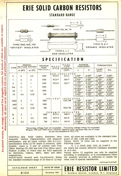
Before standardization, some manufacturers used their own color codings on the fixed resistors in their radio sets, seemingly choosing a random color for each part stock number.[nb 1] Then, in 1930,[6][7] a new code started coming into wide usage among radio makers.[nb 2] This new style encoded the resistance value of each part by means of one background paint color and usually, two additional paint marks. The Radio Manufacturers Association (RMA) gave its endorsement of this coding around 1931.[nb 3] This all-over painted, "body-end-dot" coding style, while most vividly associated with pre-war radio equipment, did live on for a while, and was still in use in the 1960s.[nb 4]
In 1935, advertisements appeared[16] for resistors coded with a sequence of color bands including one acting as a tolerance indicator; the RMA adopted a standard for this alternative style by 1941.[17] A 1943 reference book, Mechanical Practice gives an early description[18] of a further development. While the 1935 banded style only called for two digit bands before the band that specifies a "multiplying value", coded as an exponent, the new variation had three, bringing the total number of bands including the tolerance to five, as opposed to just three or four. This might seem to indicate that even at that early date, the use of a four–five rule became necessary in decoding banded resistors; in going from four to five in the total count of bands, that is where the number of digit-encoding bands increases from two to three, moving the exponent band from the third to the fourth position. In practice this was not a very important rule to memorize back then, as actual resistors showing the three-digit coding innovation remained scarce for twenty years afterwards. Eight decades later, application of the rule in some form is routinely required, but now a big part of the art of reading random-sourced resistors is, recognizing the exceptions, those tricky cases where resistance codings do not follow the rule.
Over many decades, as the organization name changed (RMA, RTMA, RETMA, EIA)[19] so was the name of the code. Though known most recently as EIA color code, the four name variations are found in books, magazines, catalogs, and other documents over more than 95 years.[nb 5]
In 1952, the International Electrotechnical Commission (IEC) published a fork of the RMA's banded resistor concept as IEC 62:1952;[32] although it did not expand to include three-digit codings following a four–five rule until the 1974 edition,[33][34] its successors and national versions/translations[nb 6] are widely referenced today. Starting with the 1968 edition it added in the widely used "RKM codes" for printed text component values on resistors and capacitors.[nb 7] Successive revisions, up to the current IEC 60062:2016,[37] added more optional features to the resistor color code, but also diverged from the EIA versions.[nb 8]
One standardized color code scheme for capacitors was in use by 1934,[40] although some radio makers kept using random-picked color codes on these longer than they did on resistors.[nb 9] (At that point, most were still calling these "condensers", an older term.) There were many variations of flat postage stamp/domino-style mica and paper dielectric capacitors with paint dots; tubular capacitors with a sequence of spots or bands also date to the 1940s. Eventually many more styles were produced using mica, paper, ceramic, glass, and plastics for the dielectric, also many tantalum types, not all codings directly published by the RMA and successors, some with dots, some with bands, some with layer-dipped paint. A 1949 article detailed nine marking types in use by that time,[43] but the proliferation of styles was just getting started then. Some later ceramic-dielectric ones from the VCR era of roughly 1980 onward look a lot like modern small axial-leaded resistors.[nb 10] Today, while color-coded "caps" are less commonly encountered, the layer-dipped "tropical fish" ones are still preferred by some, and recent reproductions of certain old tubular capacitor types have been embellished with replica "bumble-bee" color bands, suitable to make any classic-style electric guitar more authentic.[46]
Schemes for color-coding small inductors, (A.K.A. radio frequency chokes, coils, etc.) were in use by 1950;[47] as with the capacitors, some types do look a lot like modern small resistors.[nb 11] For reading, while many recent ones decode like common resistors, giving an inductance value in microhenries, older ones and some current ones are more complicated; unlike resistors, a gold or silver band may be at either end, or both, and there may be no exponent band.
Small semiconductor diodes/rectifiers were being marked with color bands by 1958.[48] Some Zener/avalanche-breakdown diodes have paint bands that indicate their main characteristic of interest, which is, their nominal rated Zener voltage.[nb 12] More commonly, a type number is indicated using one of several variants that support the U.S. JEDEC "1N" series (Glass diodes marked this way were common in the 1960s.) and European Pro Electron numbering schemes. Proprietary arbitrary codings were used by some; Hitachi made diodes with bands of designer colors such as "verdure"[53] and "yellow ocher".[54] Many later-production glass diodes have only one or two color bands, indicating a broad type category.
Several complex color coding systems for plastic-cased transistors were in use in the Soviet sphere.[55] The U.S. standard for diodes[56] allows application to transistors[nb 13] but seems to have been little used for this. Usually when color markings are found on U.S.-style small plastic transistors that have printed numbering also, they indicate a bin-sort code[nb 14] or something proprietary.
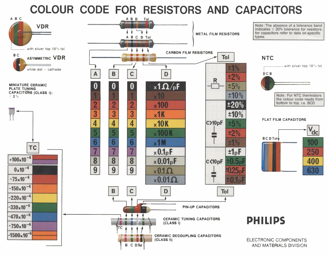
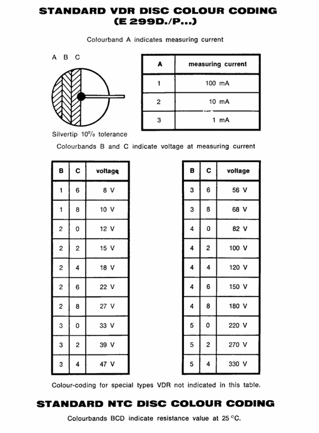
By 1970,[58] disc-shaped thermistors and voltage dependent resistors/varistors were being made with color coding in the form of layer-dipped paint;[59][60] these may be confused with some ceramic disk capacitors which are painted similarly. There are also tubular, axial-leaded styles of varistors which have their own look which differentiates them from other components.
There is even a color band coding standard for fuses, published in 1988 as IEC 127,[61] and adopted in national variants[62] covering both cartridge types that look like fuses and also, miniature types that look like modern small resistors.[nb 15]
The paint pigment used for the number seven, according to some British sources,[64] is supposed to be a "dark violet"; others in the British Commonwealth have called it mauve.[65][66][67] The general consensus of references world-wide through the decades would be a simple violet,[nb 16] although, in the early years there are several sources that call it purple,[nb 17] and even a vote for lavender[71] may be found.
A good skill to learn along with reading the codes themselves is doing the up-front step of identifying the basic type of a component, whether it is a resistor, capacitor, inductor, fuse, diode, or other. The color band system has the advantage of being readable, by people with good color vision, from multiple directions, if well-chosen paints are used. Fairly early on, some manufacturers put printed numbers on as an additional identifying aid. Some might say the system is poorly designed, as it would be simple enough to choose ten colors that work for most color blind people.
Color bands were used because they were easily and cheaply printed on tiny components. However, there were drawbacks, especially for color blind people. Overheating of a component or dirt accumulation may make it impossible to distinguish brown from red or orange. Advances in printing technology have now made printed numbers more practical on small components. The values of components in many surface mount packages are marked with printed alphanumeric codes instead of a color code.
Resistors
[edit]


Color band system
[edit]To distinguish left from right there is a gap between the C and D bands:


- The first significant figure of component value (left side)
- The second significant figure (some precision resistors have a third significant figure, and thus five bands).
- The decimal multiplier (number of trailing zeroes, or power of 10 multiplier)
- If present, indicates tolerance of value in percent (no band means 20%)
In the above example, a resistor with bands of red, violet, green, and gold has first digit 2 (red; see table below), second digit 7 (violet), followed by 5 (green) zeroes: 2700000 ohms. Gold signifies that the tolerance is ±5%.
Precision resistors may be marked with a five band system, to include three significant digits, a power of 10 multiplier (number of trailing zeroes, and a tolerance band. An extra-wide first band indicates a wire-wound resistor.[72]

Resistors manufactured for military use may also include a fifth band which indicates component failure rate (reliability); refer to MIL-HDBK-199[73] for further details.
Tight tolerance resistors may have three bands for significant figures rather than two, or an additional band indicating temperature coefficient of resistance (TCR), in units of ppm/K.
All coded components have at least two value bands and a multiplier; other bands are optional.
The standard color code per IEC 60062:2016 is as follows:
| Ring Colour | Significant numeral | Multiplier | Tolerance | TCR, Temperature coefficient | |||||
|---|---|---|---|---|---|---|---|---|---|
| Name | Code | RAL[nb 18] | Percent [%] | Letter | [ppm/K] | Letter | |||
| None | – | – | – | – | ±20 | M | – | ||
| Pink | PK | 3015 | – | ×10−3[74] | ×0.001 | – | – | ||
| Silver | SR | – | – | ×10−2 | ×0.01 | ±10 | K | – | |
| Gold | GD | – | – | ×10−1 | ×0.1 | ±5 | J | – | |
| Black | BK | 9005 | 0 | ×100 | ×1 | – | ±250 | U | |
| Brown | BN | 8003 | 1 | ×101 | ×10 | ±1 | F | ±100 | S |
| Red | RD | 3000 | 2 | ×102 | ×100 | ±2 | G | ±50 | R |
| Orange | OG | 2003 | 3 | ×103 | ×1000 | ±0.05[74] | W | ±15 | P |
| Yellow | YE | 1021 | 4 | ×104 | ×10000 | ±0.02[74][nb 19][75] | P | ±25 | Q |
| Green | GN | 6018 | 5 | ×105 | ×100000 | ±0.5 | D | ±20 | Z[nb 20] |
| Blue | BU | 5015 | 6 | ×106 | ×1000000 | ±0.25 | C | ±10 | Z[nb 20] |
| Violet | VT | 4005 | 7 | ×107 | ×10000000 | ±0.1 | B | ±5 | M |
| Grey | GY | 7000 | 8 | ×108 | ×100000000 | ±0.01[74][nb 21][nb 19][75] | L (A) | ±1 | K |
| White | WH | 1013 | 9 | ×109 | ×1000000000 | – | – | ||
| Ring Colour | Significant numeral | Multiplier | Tolerance | TCR, Temperature coefficient | |||||
|---|---|---|---|---|---|---|---|---|---|
| Name | Code | RAL[nb 18] | Percent [%] | Letter | [ppm/K] | Letter | |||
| None | – | – | – | – | ±20 | M | – | ||
| Pink | PK | 3015 | – | ×10−3[74] | ×0.001 | – | – | ||
| Silver | SR | – | – | ×10−2 | ×0.01 | ±10 | K | – | |
| Gold | GD | – | – | ×10−1 | ×0.1 | ±5 | J | – | |
| Black | BK | 9005 | 0 | ×100 | ×1 | – | ±250 | U | |
| Brown | BN | 8003 | 1 | ×101 | ×10 | ±1 | F | ±100 | S |
| Red | RD | 3000 | 2 | ×102 | ×100 | ±2 | G | ±50 | R |
| Orange | OG | 2003 | 3 | ×103 | ×1000 | ±0.05[74] | W | ±15 | P |
| Yellow | YE | 1021 | 4 | ×104 | ×10000 | ±0.02[74][nb 19][75] | P | ±25 | Q |
| Green | GN | 6018 | 5 | ×105 | ×100000 | ±0.5 | D | ±20 | Z[nb 20] |
| Blue | BU | 5015 | 6 | ×106 | ×1000000 | ±0.25 | C | ±10 | Z[nb 20] |
| Violet | VT | 4005 | 7 | ×107 | ×10000000 | ±0.1 | B | ±5 | M |
| Grey | GY | 7000 | 8 | ×108 | ×100000000 | ±0.01[74][nb 21][nb 19][75] | L (A) | ±1 | K |
| White | WH | 1013 | 9 | ×109 | ×1000000000 | – | – | ||
| Ring Colour | Significant numeral | Multiplier | Tolerance | TCR, Temperature coefficient | |||||
|---|---|---|---|---|---|---|---|---|---|
| Name | Code | RAL[nb 18] | Percent [%] | Letter | [ppm/K] | Letter | |||
| None | – | – | – | – | ±20 | M | – | ||
| Pink | PK | 3015 | – | ×10−3[74] | ×0.001 | – | – | ||
| Silver | SR | – | – | ×10−2 | ×0.01 | ±10 | K | – | |
| Gold | GD | – | – | ×10−1 | ×0.1 | ±5 | J | – | |
| Black | BK | 9005 | 0 | ×100 | ×1 | – | ±250 | U | |
| Brown | BN | 8003 | 1 | ×101 | ×10 | ±1 | F | ±100 | S |
| Red | RD | 3000 | 2 | ×102 | ×100 | ±2 | G | ±50 | R |
| Orange | OG | 2003 | 3 | ×103 | ×1000 | ±0.05[74] | W | ±15 | P |
| Yellow | YE | 1021 | 4 | ×104 | ×10000 | ±0.02[74][nb 19][75] | P | ±25 | Q |
| Green | GN | 6018 | 5 | ×105 | ×100000 | ±0.5 | D | ±20 | Z[nb 20] |
| Blue | BU | 5015 | 6 | ×106 | ×1000000 | ±0.25 | C | ±10 | Z[nb 20] |
| Violet | VT | 4005 | 7 | ×107 | ×10000000 | ±0.1 | B | ±5 | M |
| Grey | GY | 7000 | 8 | ×108 | ×100000000 | ±0.01[74][nb 21][nb 19][75] | L (A) | ±1 | K |
| White | WH | 1013 | 9 | ×109 | ×1000000000 | – | – | ||
Resistors use various E series of preferred numbers for their specific values, which are determined by their tolerance. These values repeat for every decade of magnitude: ... 0.68, 6.8, 68, 680, ... For resistors of 20% tolerance the E6 series, with six values: 10, 15, 22, 33, 47, 68, then 100, 150, ... is used; each value is approximately the previous value multiplied by 6√10. For 10% tolerance resistors the E12 series, with 12√10 as multiplier, is used; similar schemes up to E192, for 0.5% or tighter tolerance are used. The separation between the values is related to the tolerance so that adjacent values at the extremes of tolerance approximately just overlap; for example, in the E6 series 10 + 20% is 12, while 15 − 20% is also 12.
Zero ohm resistors, marked with a single black band,[76] are lengths of wire wrapped in a resistor-like body which can be mounted on a printed-circuit board (PCB) by automatic component-insertion equipment. They are typically used on PCBs as insulating "bridges" where two tracks would otherwise cross, or as soldered-in jumper wires for setting configurations.
Body-end-dot system
[edit]The "body-end-dot" or "body-tip-spot" system was used for cylindrical composition resistors sometimes still found in very old equipment (built before the Second World War); the first band was given by the body color, the second band by the color of one end of the resistor, and the multiplier by a dot or band around the middle of the resistor. The other end of the resistor was in the body color, silver, or gold for 20%, 10%, 5% tolerance (tighter tolerances were not routinely used).[77][78][79][80]
Examples
[edit]
From top to bottom:
- Green, blue, black, black, brown
- 560 ohms ±1%
- Red, red, orange, gold
- 22000 ohms ±5%
- Yellow, violet, brown, gold
- 470 ohms ±5%
- Blue, grey, black, gold
- 68 ohms ±5%
The physical size of a resistor is indicative of the power it can dissipate.
There is an important difference between the use of three and of four bands to indicate resistance. The same resistance is encoded by:
- Red, red, orange = 22 followed by 3 zeroes = 22000 (excluding default, silver, or gold tolerance)
- Red, red, black, red = 220 followed by 2 zeroes = 22000 (excluding brown or other band for tolerance)
Mnemonics
[edit]Useful mnemonics have been created to make it easier to remember the numeric order of resistor color bands:
- Betty Brown Runs Over Your Garden But Violet Gingerly Walks.
- Bad Bears Raid Our Yummy Grub But Veto Grey Waffles.
- BB ROY from Great Britain has a Very Good Wife.
The following example includes the tolerance codes — gold, silver and none:
- Bad Beer Rots Out Your Guts But Vodka Goes Well – Get Some Now.[81]
The colors are sorted in ascending order of visible light photon frequency/energy like in a rainbow to make them easy to remember and to reduce the significance of possible read errors due to color shifts and fading over time: red (2), orange (3), yellow (4), green (5), blue (6), violet (7). Black (0) has no energy, brown (1) has a little more, white (9) has everything and grey (8) is like white, but less intense.[82]
Capacitors
[edit]Capacitors may be marked with 4 or more colored bands or dots. The colors encode the first and second most significant digits of the value in picofarads, and the third color the decimal multiplier. Additional bands have meanings which may vary from one type to another. Low-tolerance capacitors may begin with the first 3 (rather than 2) digits of the value. It is usually, but not always, possible to work out what scheme is used by the particular colors used. Cylindrical capacitors marked with bands may look like resistors.
| Color | Significant digits | Multiplier | Tolerance (%) | Characteristic | DC working voltage (V) | Operating temperature (°C) | EIA/vibration (Hz) | |
|---|---|---|---|---|---|---|---|---|
| Black | 0 | 1 | — | — | — | −55 to +70 | 10 to 55 | |
| Brown | 1 | 10 | ±1 | B | 100 | — | — | |
| Red | 2 | 100 | ±2 | C | — | −55 to +85 | — | |
| Orange | 3 | 1000 | — | D | 300 | — | — | |
| Yellow | 4 | 10000 | — | E | — | −55 to +125 | 10 to 2000 | |
| Green | 5 | 100000 | ±0.5 | F | 500 | — | — | |
| Blue | 6 | 1000000 | — | — | — | −55 to +150 | — | |
| Violet | 7 | 10000000 | — | — | — | — | — | |
| Grey | 8 | — | — | — | — | — | — | |
| White | 9 | — | — | — | — | — | EIA | |
| Gold | — | — | ±5[nb 22] | — | 1000 | — | — | |
| Silver | — | — | ±10 | — | — | — | — | |
Extra bands on ceramic capacitors identify the voltage rating class and temperature coefficient characteristics.[77] A broad black band was applied to some tubular paper capacitors to indicate the end that had the outer electrode; this allowed this end to be connected to chassis ground to provide some shielding against hum and noise pickup.
Polyester film and "gum drop" tantalum electrolytic capacitors may also be color-coded to give the value, working voltage and tolerance.
Postage stamp capacitors and war standard coding
[edit]
Capacitors of the rectangular "postage stamp" form made for military use during World War II used American War Standard (AWS) or Joint Army-Navy (JAN) coding in six dots stamped on the capacitor. An arrow on the top row of dots pointed to the right, indicating the reading order. From left to right the top dots were: either black, indicating JAN mica, or silver, indicating AWS paper; first significant digit; and second significant digit. The bottom three dots indicated temperature characteristic, tolerance, and decimal multiplier. The characteristic was black for ±1000 ppm/°C, brown for ±500, red for ±200, orange for ±100, yellow for −20 to +100 ppm/°C, and green for 0 to +70 ppm/°C.
A similar six-dot code by EIA had the top row as first, second and third significant digits and the bottom row as voltage rating (in hundreds of volts; no color indicated 500 volts), tolerance, and multiplier. A three-dot EIA code was used for 500 volt 20% tolerance capacitors, and the dots signified first and second significant digits and the multiplier. Such capacitors were common in vacuum tube equipment and in surplus for a generation after the war but are unavailable now.[83]
Inductors
[edit]Standards IEC 60062 / EN 60062 do not define a color code for inductors, but manufacturers of small inductors use the resistor color code, typically encoding inductance in microhenries.[84] A white tolerance ring is used by TDK to indicate custom specifications.[84]
Diodes
[edit]The part number for small JEDEC "1N"-coded diodes – in the form "1N4148" – is sometimes encoded as three or four rings in the standard color code, omitting the "1N" prefix. The 1N4148 would then be coded as yellow (4), brown (1), yellow (4), grey (8).
Wire
[edit]Transformer
[edit]Power transformers used in North American vacuum-tube equipment were often color-coded to identify the leads. Black was the primary connection, red secondary for the B+ (plate voltage), red with a yellow tracer was the center tap for the B+ full-wave rectifier winding, green or brown was the heater voltage for all tubes, yellow was the filament voltage for the rectifier tube (often a different voltage than other tube heaters). Two wires of each color were provided for each circuit, and phasing was not identified by the color code.
Audio transformers for vacuum tube equipment were coded blue for the finishing lead of the primary, red for the B+ lead of the primary, brown for a primary center tap, green for the finishing lead of the secondary, black for grid lead of the secondary, and yellow for a tapped secondary. Each lead had a different color since relative polarity or phase was more important for these transformers. Intermediate-frequency tuned transformers were coded blue and red for the primary and green and black for the secondary.[83]
Other
[edit]Wires may be color-coded to identify their function, voltage class, polarity, phase or to identify the circuit in which they are used. The insulation of the wire may be solidly colored, or where more combinations are needed, one or two tracer stripes may be added. Some wiring color codes are set by national regulations, but often a color code is specific to a manufacturer or industry.
Building wiring under the US National Electrical Code and the Canadian Electrical Code is identified by colors to show energized, neutral, and grounding conductors, and to identify phases. Other color codes are used in the UK and other areas to identify building wiring or flexible cable wiring.
Mains electrical wiring, both in a building and on equipment, was once usually red for live, black for neutral, and green for earth, but this was changed as it was a hazard for color-blind people, who might confuse red and green; different countries use different conventions. Red and black are frequently used for positive and negative of battery or other single-voltage DC wiring.
Thermocouple wires and extension cables are identified by color code for the type of thermocouple; interchanging thermocouples with unsuitable extension wires destroys the accuracy of the measurement.
Automotive wiring is color-coded but standards vary by manufacturer; differing SAE and DIN standards exist.
Modern personal computer peripheral cables and connectors are color-coded to simplify connection of speakers, microphones, mice, keyboards and other peripherals, usually according to coloring schemes following recommendations such as PC System Design Guide, PoweredUSB, ATX, etc.
A common convention for wiring systems in industrial buildings is: black jacket – AC less than 1,000 volts, blue jacket – DC or communications, orange jacket – medium voltage 2,300 or 4,160 V, red jacket 13,800 V or higher. Red-jacketed cable is also used for relatively low-voltage fire alarm wiring, but has a much different appearance.
Local area network cables may also have non-standardised jacket colors identifying, for example, process control network vs. office automation networks, or to identify redundant network connections, but these codes vary by organization and facility.
See also
[edit]
- E series of preferred numbers (IEC 60063) – series of preferred resistance and capacitance values
- Color code
- Electrical wiring – AC power wiring inside buildings, including standard color codes
Notes
[edit]- ↑ Decoding keys, useful for restoration projects, are still available for some brands including FADA,[3] Zenith,[4] Philco and Bosch.[5]
- ↑ Most U.S. suppliers seem to have adopted the code by 1933; Atwater Kent was perhaps the slowest to change, possibly using "a few" proprietary ones[8] until its closure in 1936.
- ↑ This dating comes from the observation that the apparent earliest references to the term "RMA resistor color code" appear in periodicals dated 1931, none before the April issues,[9][10][11] and that one mention in a July issue[12] still calls it a "proposed standard." These are product announcements by resistor makers who would have no reason to "sit on" and delay the news of the standard's approval. An unnamed description of the code was printed in a February issue[13] of that year; an RMA-branded color standard for the battery wires of radios is dated from at least 1927.[14]
- ↑ A 1961 Erie Company of the U.K. catalog shows a late usage of this style.[15]
- ↑ Numerous separate documents make up the EIA standard family. A list of RMA-descendent color coding standards might include EIA-RS-172-B,[20] for carbon composition resistors with two digit bands, plus EIA-RS-344[21] for wirewound resistors, (Basically just saying the first band is double-width,) and EIA-RS-279 (from 1963; it is hard to find this on-line, but there is an RCA Engineering Dept. excerpt[22] showing "grey" as 0.05% tolerance, and a 1963 journal piece[23] showing a three-digit, "Film (EIA)" resistor whose coding and tolerances match the excerpt.) plus EIA-RS-196-A[24] (1970; takes in the codes from RS-279 only changing "grey" to "gray") for film resistors with three digit bands. Then there is EIA-RS-198-B[25] for flat and tubular ceramic capacitors, EIA RS-335[26] for small tubular "composition" capacitors, EIA-RS-153-B [27] for flat mica capacitors, the elusive EIA-RS-228 giving at least one of the many color marking styles of tantalum capacitors, (One reference[28] for this is incomplete, giving a color table but no applicable picture of the marking style.) EIA-IS-48[29] for inductors, (as an "Interim Standard", this possibly was only in force for a limited time,) and EIA-RS-236-B of 1963 and the later JEDEC 236-C[30] for 1N-series diodes. EIA-RS-164 or RMA REC-118 may possibly define the color code for "bumble-bee" tubular paper-dielectric capacitors; maybe someone has a copy. And somewhere there should be an obscure RMA standard, circa 1939, for the rare six-band, three-digit tubular capacitors that read from the middle-out.[31]
- ↑ The RKM code page lists many of these, which mostly use the number 60062, although in past years there were the British BS 1852:1975, Indian IS 8186-1976, and Japanese JIS C 5062, and for a time Germany split it into DIN 41429 for color codes,[35] DIN 41314 for date codes, and DIN 40825 for "RKM" codes.
- ↑ Contrary to statements seen in this space for about eight years, IEC 60062 never had recommendations for using color coding on capacitors, although national versions such as India's IS 8186-1976[36] (Without giving appropriate sequence diagrams or examples, however,) may have made such a suggestion.
- ↑ A way to gauge which authority each resistor manufacturer follows is, by whether their published code-key makes the rare grey/gray tolerance band mean 0.01% as IEC 60062 defined it in 2016, or 0.05% like EIA RS-279[38] [39] from 1963. Also, for the orientation clue on five-band resistors, (if not combining both indications,) do they widen the fifth band, or widen the last inter-band gap?
- ↑ For example, industry giant Philco shows no use of standardization on its mica capacitors or "condensers" in 1937,[41] and R.C.A. used proprietary color spot codes on many ceramic capacitors following the E12 value sequence which only came into general use post-1940.[42]
- ↑ These usually have three to five color bands on a glossy background, either ranging from yellow to light green, or pink, or light blue. Typical sources/data sheets may only mention a neutral yellowish green and pink.[44][45] The rarer light blue ones usually distinguish themselves from similar-colored common resistors by having only four bands, of which none is a Shiny. But there may also be blue ones with five bands.
- ↑ On the most common ones including many from China brands, often the distinguishing clues will be a background color of a shade of turquoise or bright lemon-lime, a graceful curvy profile, and a shorter, broader aspect ratio, slightly less stretched-out compared to typical resistors. But some, including recent ones, may instead sport a beige or brown background, as found on many resistors, just to make it interesting.
- ↑ In several Panasonic product lines, a coding of two bands on the glass body, with head-end band widened, is used for voltages 10 volts and up, and gives a direct two-digit voltage coding. Values under 10 volts are indicated with three bands, with the first two giving Zener voltage in tenths of a volt, and the third band being a flag or dummy, always a duplicate of the second. There typically is one more band on the head-end wire lead, (rather than on the glass part,) giving a finer resolution reading of the measured Zener voltage.[49][50][51][52]
- ↑ The word "diode" is absent from the standard, as it covers semiconductor devices in general, although for transistors of other than cylindrical shape, it would give no specific guidance on how the sequence direction should be indicated.
- ↑ The Texas Instruments 2N3708 transistor is a rare documented example of this.[57]
- ↑ These[63] have four color bands including a widened, often red, fourth band, typically on a pea-soup green background. Littelfuse may still offer these by special order; the current standard product has printed markings instead.
- ↑ The RMA and its successors generally use violet in their standards including the earliest published versions,[68] with the exception of calling for purple on mica capacitors[69].
- ↑ An Ohmite advertisement from 1932 is an example.[70]
- 1 2 3 For illustration only. IEC 60062:2016 and IEC 60757:1982 do not specify or intend to specify color boundaries and properties, and colors shown here as example are applied for the purpose of consistent illustration only.
- 1 2 3 4 5 6 Before yellow and grey colored rings were assigned to tolerance values of ±0.02% and ±0.01% with IEC 60062:2016, some manufacturers used yellow and grey as substitute for gold (±5%) and silver (±10%) colored rings in high-voltage resistors to avoid metal particles in the lacquer.
- 1 2 3 4 5 6 Any temperature coefficient not assigned its own letter shall be marked "Z", and the coefficient found in other documentation.
- 1 2 3 Before a grey colored ring was assigned to a tolerance of ±0.01% with IEC 60062:2016, some manufacturers used a grey colored ring to indicate a non-standardized tolerance of ±0.05%.
- ↑ ±5% or ±0.5 pF, whichever is greater.
References
[edit]- ↑ "Advertisement" (PDF). Radio Broadcast: 641. February 1925.
- ↑ "Standard Color Designations for Cords Used for Outside Connections in Radio Receivers" (PDF). Radio Broadcast: 1034. April 1925.
- ↑ "FADA RADIO & ELECTRIC CORP.". Perpetual Troubleshooter's Manual, Volume IV (PDF). 1934. p. 4-4.
- ↑ Perpetual Trouble Shooter's Manual (PDF). 1933. p. 1-18 Zenith.
- ↑ "Resistor Color Codes" (PDF). Antique Radio Classified: 18. March 1995.
- ↑ Rider, John F.; Muhleman, M. L., eds. (April 1932). "Color coding" (PDF). Service - A Monthly Digest of Radio and Allied Maintenance. 1 (3). New York City, NY, USA: John F. Rider Publications, Inc.: 62. Retrieved 2019-11-15.
Color coding of resistances used in receivers is not always according to the standard recommended by the RMA. Most of the manufacturers now are using this code. The following is a partial tabulation of receiver manufacturers and comments concerning their use of the body, tip and dot system. [...]
(NB. Part 1/2 of a list of when each radio manufacturer first started using RMA color coded resistors.) - ↑ Rider, John F.; Muhleman, M. L., eds. (May 1932). "Color coding - Continued from April issue" (PDF). Service - A Monthly Digest of Radio and Allied Maintenance. 1 (4). New York City, NY, USA: John F. Rider Publications, Inc.: 89. Retrieved 2019-11-15. (NB. Part 2/2 of a list of when each radio manufacturer first started using RMA color coded resistors.)
- ↑ "A-K COLOR CODINGS" (PDF). Radio Today: 42. January 1937.
- ↑ "For Color-Coded Resistors" (PDF). Radio Retailing: 47. April 1931.
- ↑ "Color code indicator" (PDF). Electronics: 607. April 1931.
- ↑ "Resistor Assortment" (PDF). Radio News: 913. April 1931.
- ↑ "Strays" (PDF). QST: 26. July 1931.
- ↑ "RESISTOR MARKINGS" (PDF). Radio-Craft: 506. February 1931.
- ↑ Catalog, American Radio Transmitter 1927 (PDF). 1927. p. 71.
- ↑ "Erie Solid Carbon Resistors". Catalogue. November 1961. p. R100. Archived from the original on 2025-01-26.
- ↑ "Advertisement" (PDF). Electronics: 36. February 1935.
- ↑ "Resistance". THE RADIO ENGINEERING HANDBOOK (PDF). 1941. p. 62.
- ↑ "9. RADIO MANUFACTURERS' ASSOCIATION STANDARDS". Mechanical Practice (PDF). Radio Matériel School. 1943. p. 74. Archived from the original on 2025-02-25.
- ↑ "JEDEC History". JEDEC. Archived from the original on 2007-09-29. Retrieved 2007-09-29.
- ↑ "EIA STANDARD Fixed Composition Resistors RS-172-B" (PDF). March 1975. Archived (PDF) from the original on 2025-10-26.
- ↑ "EIA STANDARD Low Power, Insulated Fixed Wirewound Resistors RS-344" (PDF). January 1968. Archived (PDF) from the original on 2025-08-26.
- ↑ "STANDARDIZING NOTICE EIA STANDARD RS-279" (PDF). August 1963. Archived (PDF) from the original on 2026-04-09.
- ↑ "Electronic Color Codes" (PDF). Electronics: 39. 1963-11-15.
- ↑ "FIXED FILM RESISTORS - PRECISION AND SEMIPRECISON RS-196-A" (PDF). 1970. Archived (PDF) from the original on 2025-08-26.
- ↑ "EIA STANDARD Ceramic Dielectric Capacitors RS-198-В" (PDF). October 1971. Archived (PDF) from the original on 2025-08-26.
- ↑ Nuclear Electronics Laboratory Manual (PDF). 1984. p. 25. Archived (PDF) from the original on 2025-03-19.
- ↑ "MOLDED AND DIPPED MICA CAPACITORS (WIRE LEAD STYLES) RS-153-B" (PDF). 1972. Archived (PDF) from the original on 2025-08-26.
- ↑ Nuclear Electronics Laboratory Manual (PDF). 1984. p. 24. Archived (PDF) from the original on 2025-03-19.
- ↑ "EIA INTERIM STANDARD Axial Lead Fixed Radio Frequency (RF) Coils EIA/IS-48" (PDF). Archived (PDF) from the original on 2025-10-21.
- ↑ "Color Coding, Multi Component Types" (PDF). 1986. p. 4. Archived (PDF) from the original on 2025-10-21.
- ↑ THE RADIOTRON Designer's Handbook (PDF). November 1941. p. 313.
- ↑ "Publication 62 COLOUR CODE for FIXED RESISTORS" (PDF). 1952. Archived (PDF) from the original on 2025-10-21.
- ↑ "Publication 62 1968 Marking codes for values and tolerances of resistors and capacitors" (PDF). 1968. Archived (PDF) from the original on 2025-10-21.
- ↑ "Publication 62 1974 Marking codes for resistors and capacitors" (PDF). 1974. Archived (PDF) from the original on 2025-10-21.
- ↑ "DEUTSCHE NORMEN Farbkennzeichnung von Widerständen DIN 41429" (PDF). 1978. Archived (PDF) from the original on 2026-03-06.
- ↑ "MARKING CODES FOR VALUES AND TOLERANCES OF RESISTORS AND CAPACITORS" (PDF). 1976. p. 3.
- ↑ "IEC 60062:2016-07" (6 ed.). July 2016. Archived from the original on 2018-07-23. Retrieved 2018-07-23.
- ↑ "STANDARDIZING NOTICE EIA STANDARD RS-279" (PDF). August 1963. Archived (PDF) from the original on 2026-04-09.
- ↑ EIA RS-279: Color code for film resistors. Electronic Industries Alliance. 1963-08-01.
- ↑ "Use of the Color Code for Fixed Condensers" (PDF). Radio World: 15. 1934-09-22.
- ↑ "Color Code for Philco Mica Condensers" (PDF). Philco Serviceman: 3. May 1937.
- ↑ "RCA Ceramic Capacitor Color Code Charts" (PDF). Service: 49. May 1945.
- ↑ "How to Read the Condenser Color Codes" (PDF). National Radio News: 8. February–March 1949.
- ↑ "Panasonic Axial Lead Ceramic Capacitors" (PDF). p. 3. Archived (PDF) from the original on 2026-04-05.
- ↑ "Taiyo Yuden Products Tubular Ceramic Capacitors" (PDF). 1984. p. 3. Archived (PDF) from the original on 2026-04-05.
- ↑ "Centralab Bumblebee Tone Capacitor .022uF PIO 300V". 2025. Archived from the original on 2025-03-16.
- ↑ "Advertisement, MILO Radio & Electronics Corp" (PDF). Electronics: 184. March 1950.
New CLA and CL-1 insulated chokes, readily identified with RMA color coding in microhenries.
- ↑ Metalic rectifiers and Crystal Diodes (PDF). September 1958. p. 4-13.
- ↑ "MAZ2000 Series (MA2000 Series)" (PDF). Archived (PDF) from the original on 2025-10-08.
- ↑ "MAZ4000 Series (MA4000 Series)" (PDF). 2001. Archived (PDF) from the original on 2025-10-08.
- ↑ "MAZ4000N Series (MA4000(N) Series)" (PDF). 2001. Archived (PDF) from the original on 2025-10-08.
- ↑ "MAZ7000 Series (MA7000 Series)" (PDF). March 2001. Archived (PDF) from the original on 2026-09-07.
- ↑ "Silicon Epitaxial Planar Diode for High Voltage Switching" (PDF). 1995. Archived (PDF) from the original on 2021-12-13.
- ↑ "HZK Series Silicon Epitaxial Planar Zener Diodes for Stabilized Power Supply" (PDF). 1999. Archived (PDF) from the original on 2025-07-05.
- ↑ "Маркировка отечественных п/п приборов в корпусе KТ&26 (ТО&92)". МАРКИРОВКА ЭЛЕКТРОННЫХ КОМПОНЕНТОВ ОПРЕДЕЛИТЕЛЬ (PDF). p. 26. Archived from the original (PDF) on 2018-07-12.
- ↑ "Color Coding, Multi Component Types" (PDF). 1986. p. 4. Archived (PDF) from the original on 2025-10-21.
- ↑ Preferred Semiconductors and Components from Texas Instruments (PDF). 1969. p. 1436.
- ↑ PHILIPS DATA HANDBООK COMPONENTS AND MATERIALS (PDF). December 1970. p. C27, C43, C64, C188. Archived from the original (PDF) on 2025-03-06.
- ↑ "Colour Code for Resistors and Capacitors". Archived from the original on 2025-11-08.
- ↑ "Standard VDR Disc Colour Coding". Archived from the original on 2024-10-12.
- ↑ "International Standard 127-1 preview". December 1988. Archived from the original on 2026-01-30.
- ↑ "Indian Standard MINIATURE FUSES IS/lEC 60127-1 : 2006" (PDF). p. 13.
- ↑ "FUSES SUBMINIATURE PICO II® Fast-Acting Type" (PDF). Archived (PDF) from the original on 2025-06-26.
- ↑ Radio Data Book (PDF). 1950. p. 7.
- ↑ "Reading Resistor Values" (PDF). Practical Television: 459. June 1961.
- ↑ "Colour-Coding of Low-Valued Resistors" (PDF). Radio and Electrical Review: 18. August 1958.
a 47 ohm resistor would read "Yellow, Mauve, Black"
- ↑ A Guide to HiFi (PDF). 1977. p. 137.
- ↑ The Radio Engineering Handbook (PDF). 1933. p. 49.
- ↑ "MOLDED AND DIPPED MICA CAPACITORS (WIRE LEAD STYLES) RS-153-B" (PDF). 1972. p. 17. Archived (PDF) from the original on 2025-08-26.
- ↑ "OHMITE" (PDF). Radio Retailing: 42. February 1932.
- ↑ Official Radio Service Manual (PDF). 1933. p. 563.
- ↑ Westman, H. P., ed. (1968). Reference Data for Radio Engineers (5 ed.). ITT / Howard W. Sams. pp. 5-8 – 5-10. LCCN 43-14665.
- ↑ "MIL-HDBK-199C" (PDF).
- 1 2 3 4 5 6 7 8 9 10 11 12 "IEC 60062:2016-07" (6 ed.). July 2016. Archived from the original on 2018-07-23. Retrieved 2018-07-23.
- 1 2 3 4 5 6 VR37 High ohmic/high voltage resistors (PDF). Vishay. 2015. Archived from the original (PDF) on 2016-09-10.
- ↑ "NZO series zero-ohm resistors". NIC Components Corp. Archived from the original on 2009-01-04.
- 1 2 Buttner, Harold H.; Kohlhaas, H. T.; Mann, F. J., eds. (1946). "Chapter 3: Audio and radio design". Reference Data for Radio Engineers (PDF) (2 ed.). Federal Telephone and Radio Corporation (FTR). pp. 52, 57. Archived (PDF) from the original on 2018-05-16. Retrieved 2020-01-03.
- ↑ "How To Read Old Style Resistors" (PDF). 2006-10-03. Archived (PDF) from the original on 2016-12-19. Retrieved 2016-12-19.
- ↑ "RMA Resistor and Flexible Resistor Color Codes". Archived from the original on 2016-12-19. Retrieved 2016-12-19.
- ↑ "The Antique Resistor Color Code" (PDF). Archived (PDF) from the original on 2016-12-19. Retrieved 2016-12-19.
- ↑ Campbell, Dean. "The Mnemonics Page". Bradley University Chemistry Department.
- ↑ Clement, Preston R.; Johnson, Walter Curtis (1960). Electrical Engineering Science. McGraw-Hill. p. 115.
- 1 2 Dorbuck, Tony, ed. (1978) [1977]. The Radio Amateur's Handbook (5 ed.). Connecticut, USA: The American Radio Relay League. pp. 553–554. LCCN 41-3345. no ISBN.
- 1 2 "RF General" (PDF). TDK.


External links
[edit]- Online resistor calculators
- Multi-purpose resistor code converter (4 and 5 band, mobile-friendly, shows nearest standard value)
- 6 band resistor color code calculator (easy lookup, 4 and 5 band calculators also available)
- Historical charts